Wind Tunnel Testing
28/02/20 17:00
Here we are in the middle of winter and I've been grounded for weeks. Not that we haven't had some decent flying days along the way, but if it wasn't weather it was a mechanical problem or just a schedule issue that kept me out of the air. And I haven’t been able to hang around the airport to find out what news others have. So, this month’s blog will pull some material out of the archives of my early career to take a look at wind tunnel testing.
One of the most interesting jobs I’ve had was working as a test engineer for The Boeing Company. Boeing hired me right out of college, and started me in the Weapons Effect Lab. There we loaded aircraft wing sections into a test fixture and fired all kinds of projectiles at them, everything from ice balls to 23mm HEI anti-aircraft rounds.
Next, I worked in structural testing where we put the composite wing replacement for the A-6 Intruder through full scale testing. And I worked in flight test, flying up and down the west coast in an experimental 757. But the most interesting work I did was in aerodynamics research.
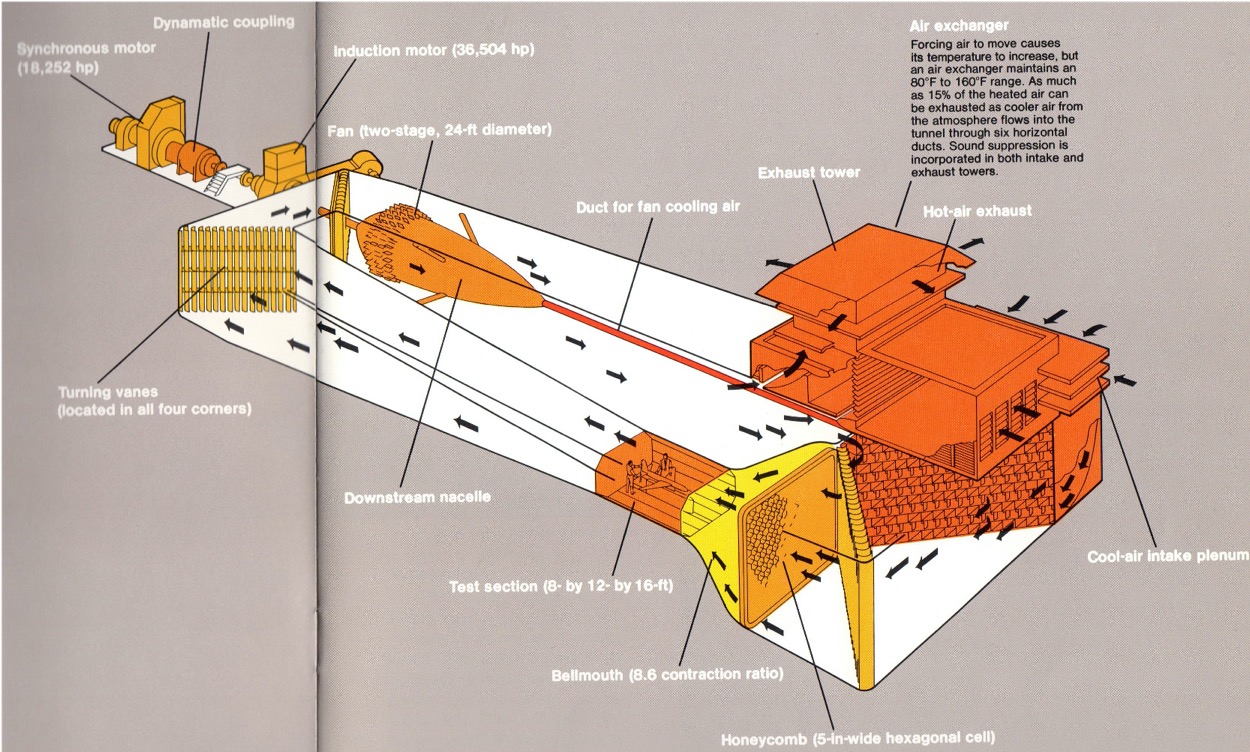
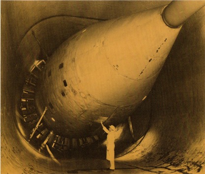
Figure 1: Boeing Transonic Wind Tunnel, courtesy The Boeing Company.
Next to Boeing Field just south of Seattle is the Edmund T. Allen Memorial Aeronautical Laboratories. When I was there in the early nineties, the facility included a number of wind tunnels, the most active of which was the Transonic Wind Tunnel.
The Transonic Wind Tunnel’s 8'x12'x16' test section accommodates full and half models in sting, plate, and floor mounted configurations. Notice in the figure above the massive structure required to smoothly push air through the test section at speeds from approximately 0.7 Mach to Mach 1.2.
This closed-loop wind tunnel is rectangular. Large turning vanes turn the air 90 degrees around each corner, and a hexagonal honeycomb section straightens the air flow before it enters the test chamber. (See Figure 1.)
Air moving at up to 900 miles per hour gets very hot! Why? Friction. Therefore, the system must ingest cool air from outside and exhaust the hot air to maintain reasonable temperatures.
Air in the Transonic Wind Tunnel is driven by a massive two-stage fan system powered by electric motors totaling more than 54,000 horsepower.
Photo: Boeing Transonic Wind Tunnel fan, courtesy The Boeing Company.
The supersonic tunnel was used to test models at up to Mach 4 (depending on the model size). This tunnel was a blow-down configuration. Two huge 38-ft. diameter spheres at one end were pressurized, the gates opened, and whoosh!
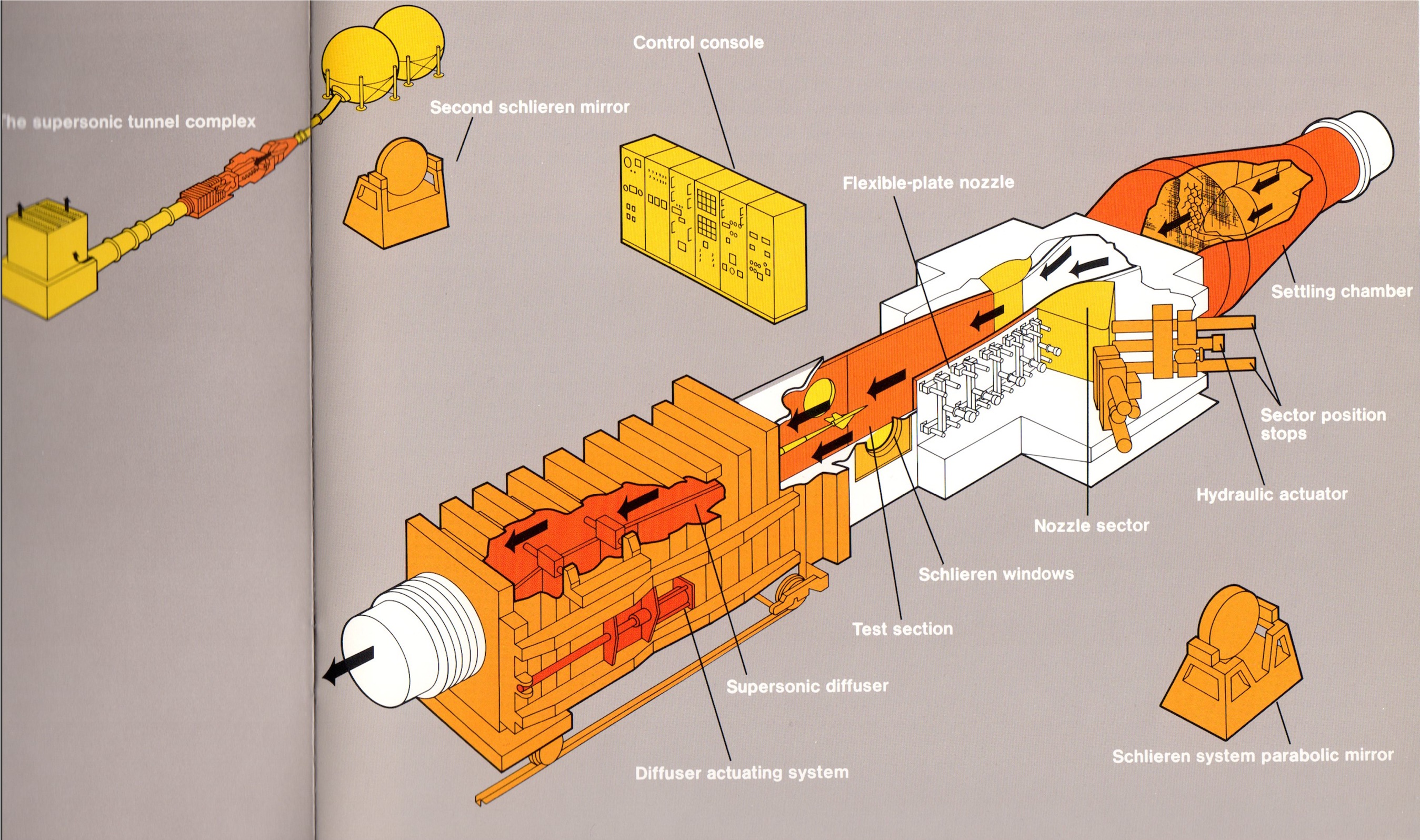
Figure 2: Boeing Supersonic Wind Tunnel, courtesy The Boeing Company.
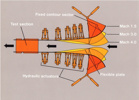
To control airspeed, hydraulic actuators varied the contour of the intake nozzle.
Figure 3: Boeing Supersonic Wind Tunnel inlet.
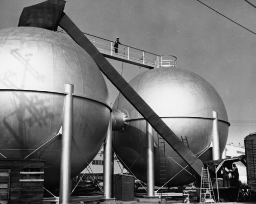
The large spheres were filled with millions of empty pop and beer cans. Why? Temperature control of the expanding air. (After Boeing merged with McDonnell Douglas, the supersonic wind tunnel at Boeing Field became redundant and was demolished in 2016. Collectors are going nuts trying to get their hands on those cans!)
Boeing's Aero Labs also included several smaller research wind tunnels, and Boeing often contracted for testing time in other wind tunnels around the world, such as NASA Ames, University of Washington, and others.
The picture below shows yours truly (far right) at the RAE’s Farnborough site. Boeing used this low-speed tunnel to test certain landing and take-off configurations.
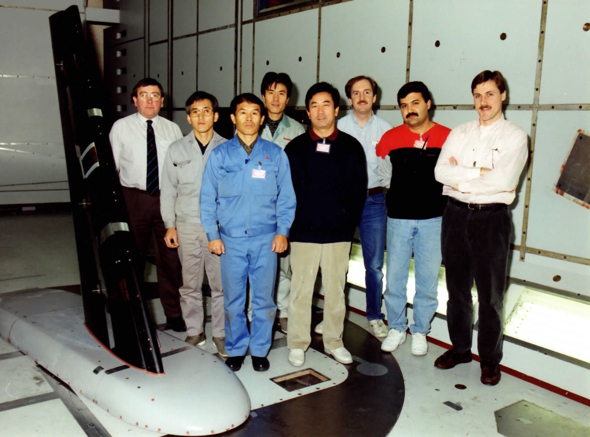
Photo: Engineers from Boeing, a Boeing partner from Japan, and the RAE in the low speed wind tunnel at Farnborough England, November, 1992.
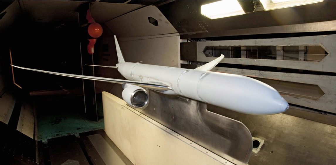
My job was instrumentation. Running a model in the wind tunnel isn’t very useful unless you can accurately measure the effects of the air flowing around the geometry of the model.
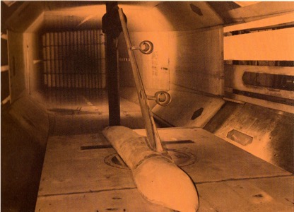
During testing, the model is positioned at various angles of attack where we measure two primary things: the forces and moments acting on the model, and pressure across its surfaces.
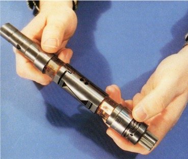 A single six-component balance measures the three forces (lift, drag, side) and three moments (pitch, roll, yaw) involved in flight dynamics. You may remember learning about four forces that act on an aircraft: thrust and drag, lift and weight. But really, thrust negates (is the opposite of) drag, and lift negates gravity (weight), so these are just two forces. The third is side or lateral force, which pilots are not typically concerned with but aerodynamicists are, so we measure it in the wind tunnel.
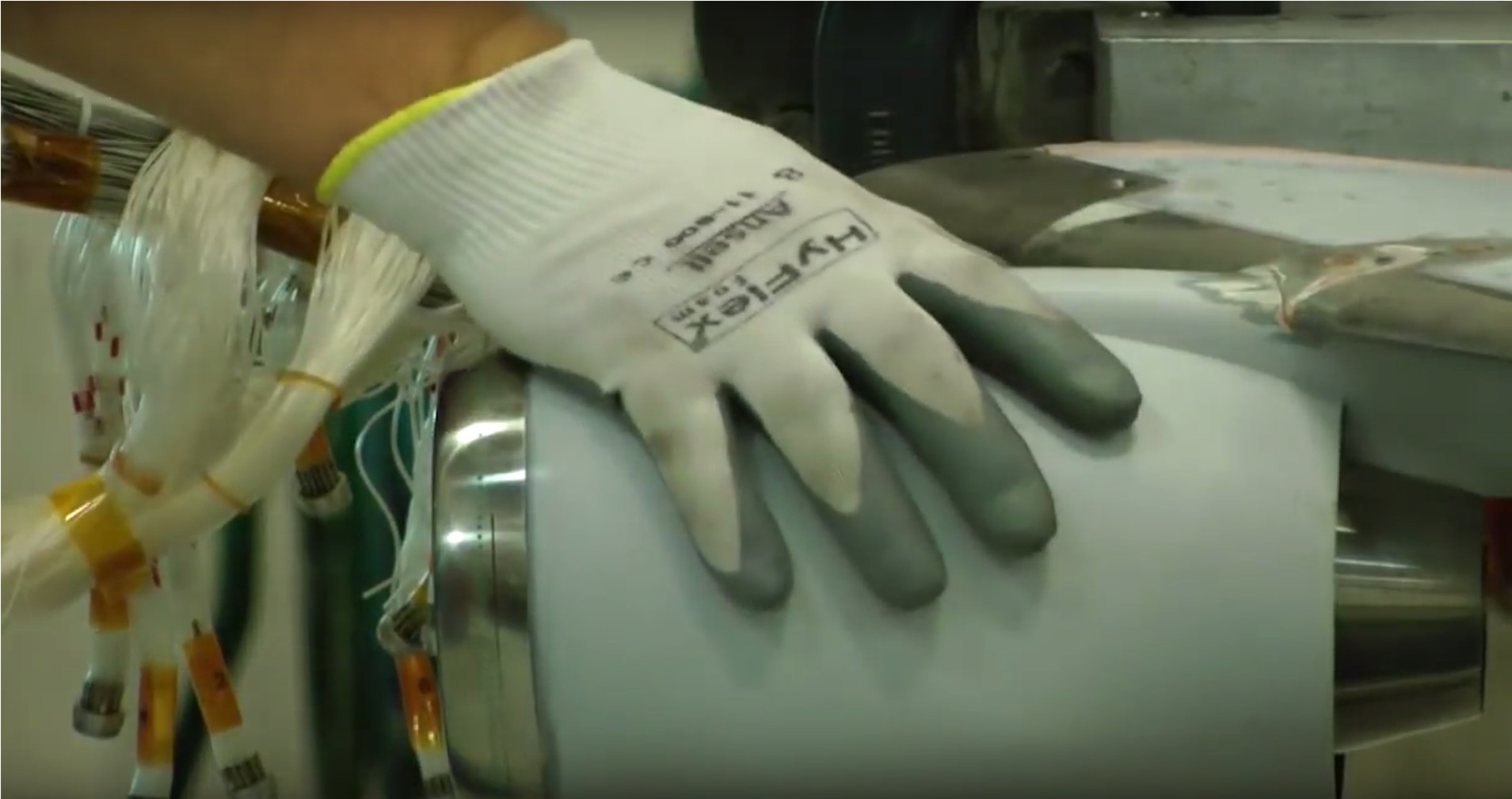
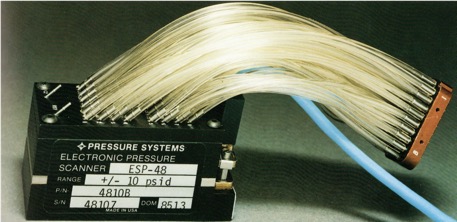 Ideally, we measure pressure over all surfaces of the aircraft model. This is done with hundreds or sometimes thousands of tiny pressure taps plumbed from the surface back to a pressure sensor (transducer). The example shown in the picture is a 48-port pressure scanner. A typical model would have many of these installed inside.
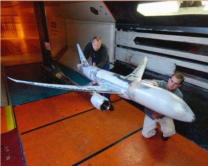
You can imagine the skill and precision required to construct an accurate model with all of this instrumentation inside. These models, made by master machinists, cost millions of dollars each to produce.
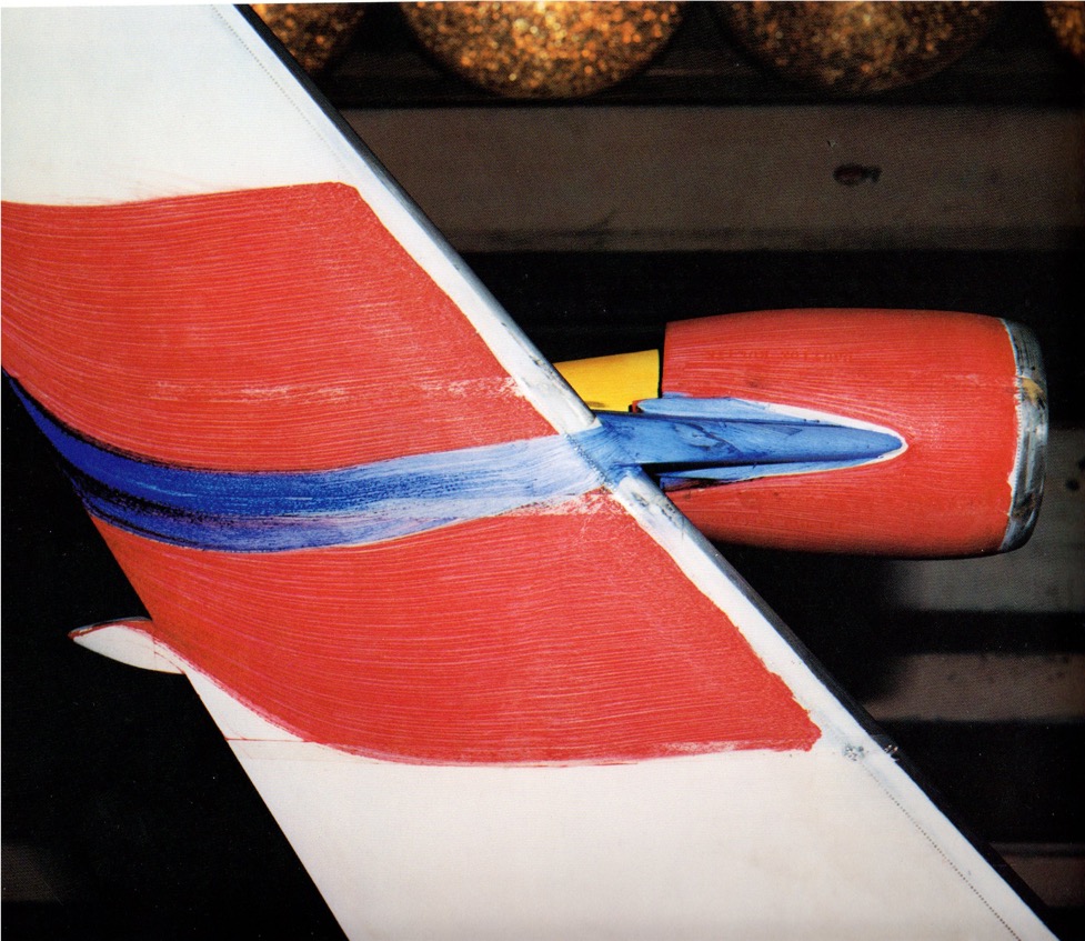
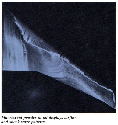
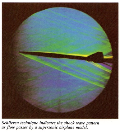
Knowledge can also be gained without instrumentation, using visual flow indicators, such as oil-based colored and fluorescent paints, or from Schlieren imaging.
My experience with wind tunnel testing is now nearly thirty years old. No doubt there have been many advances since then. In particular, computer modeling has replaced much of the very expensive process of physical model construction and testing. One might even classify wind tunnel testing as “old school”. But I hope you have found this interesting none the less.
—Alan Collins, Vice President EAA Chapter 1373
One of the most interesting jobs I’ve had was working as a test engineer for The Boeing Company. Boeing hired me right out of college, and started me in the Weapons Effect Lab. There we loaded aircraft wing sections into a test fixture and fired all kinds of projectiles at them, everything from ice balls to 23mm HEI anti-aircraft rounds.
Next, I worked in structural testing where we put the composite wing replacement for the A-6 Intruder through full scale testing. And I worked in flight test, flying up and down the west coast in an experimental 757. But the most interesting work I did was in aerodynamics research.
Figure 1: Boeing Transonic Wind Tunnel, courtesy The Boeing Company.
Next to Boeing Field just south of Seattle is the Edmund T. Allen Memorial Aeronautical Laboratories. When I was there in the early nineties, the facility included a number of wind tunnels, the most active of which was the Transonic Wind Tunnel.
The Transonic Wind Tunnel’s 8'x12'x16' test section accommodates full and half models in sting, plate, and floor mounted configurations. Notice in the figure above the massive structure required to smoothly push air through the test section at speeds from approximately 0.7 Mach to Mach 1.2.
This closed-loop wind tunnel is rectangular. Large turning vanes turn the air 90 degrees around each corner, and a hexagonal honeycomb section straightens the air flow before it enters the test chamber. (See Figure 1.)
Air moving at up to 900 miles per hour gets very hot! Why? Friction. Therefore, the system must ingest cool air from outside and exhaust the hot air to maintain reasonable temperatures.
Air in the Transonic Wind Tunnel is driven by a massive two-stage fan system powered by electric motors totaling more than 54,000 horsepower.
Photo: Boeing Transonic Wind Tunnel fan, courtesy The Boeing Company.
The supersonic tunnel was used to test models at up to Mach 4 (depending on the model size). This tunnel was a blow-down configuration. Two huge 38-ft. diameter spheres at one end were pressurized, the gates opened, and whoosh!
Figure 2: Boeing Supersonic Wind Tunnel, courtesy The Boeing Company.
To control airspeed, hydraulic actuators varied the contour of the intake nozzle.
Figure 3: Boeing Supersonic Wind Tunnel inlet.
The large spheres were filled with millions of empty pop and beer cans. Why? Temperature control of the expanding air. (After Boeing merged with McDonnell Douglas, the supersonic wind tunnel at Boeing Field became redundant and was demolished in 2016. Collectors are going nuts trying to get their hands on those cans!)
Boeing's Aero Labs also included several smaller research wind tunnels, and Boeing often contracted for testing time in other wind tunnels around the world, such as NASA Ames, University of Washington, and others.
The picture below shows yours truly (far right) at the RAE’s Farnborough site. Boeing used this low-speed tunnel to test certain landing and take-off configurations.
Photo: Engineers from Boeing, a Boeing partner from Japan, and the RAE in the low speed wind tunnel at Farnborough England, November, 1992.
My job was instrumentation. Running a model in the wind tunnel isn’t very useful unless you can accurately measure the effects of the air flowing around the geometry of the model.
During testing, the model is positioned at various angles of attack where we measure two primary things: the forces and moments acting on the model, and pressure across its surfaces.
You can imagine the skill and precision required to construct an accurate model with all of this instrumentation inside. These models, made by master machinists, cost millions of dollars each to produce.
Knowledge can also be gained without instrumentation, using visual flow indicators, such as oil-based colored and fluorescent paints, or from Schlieren imaging.
My experience with wind tunnel testing is now nearly thirty years old. No doubt there have been many advances since then. In particular, computer modeling has replaced much of the very expensive process of physical model construction and testing. One might even classify wind tunnel testing as “old school”. But I hope you have found this interesting none the less.
—Alan Collins, Vice President EAA Chapter 1373